Post 12 - Now Where Have I Been (2)
Hi Again Folks – it’s been a while!
Firstly, let me say that I hope that all of you reading this have not been seriously impacted, health wise, by this awful pandemic we are going through, either directly or via friends & family. I have seen a number of worldwide epidemics in my life (AIDS, Ebola, Asian Flu, to name a few) but none have been as far reaching or as devastating as this has. It’s effect on lives around the world is truly unprecedented, and our thoughts and sympathies go out to those who have been affected by it. Before reading on, please pause for a moment to think about those whose lives have been tragically affected by this terrible disease, and to offer up a prayer in whatever religion, creed or belief system you follow, for those who have been touched by it.
Now, let’s put our dark feelings aside, and move on to lighter matters.
I’ve titled this post “So Where Have I Been?”, as I thought I’d give a bit of a general overview of what we’ve been working on since the last post, from before the Pandemic hit. Well, we have NOT been “Out of my brain on the 5:15”, for those fans of The Who out there! (Spookily, as I write this, I am wearing my Who ‘T’ shirt from the 2017 tour!). No, indeed far from it. We have been busy little bees, albeit hampered by working from home for a good deal of the time, so not having access to our lab to do much construction. However, that hasn’t stopped us from undertaking some exciting work in developing software, strengthening our code base of in-house code developed from first principles on the robotics side, to extending other aspects of development to continue our foray into the realms of AI!
Let me begin with a recap. Phoenix Labs was set up as a AI & Robotics R&D company, with the goal of developing a working prototype of a robot capable of providing a level of care to people in their own homes. The people requiring care would be people who are ageing or who have some form of physical disability. The care provided would be in the form of undertaking tasks which the person may find difficulty in doing themselves, and ideally include bringing drinks on demand, bringing food (including heating pre-prepared meals in a microwave, or equivalent), and acting as a companion by engaging in some level of conversation. The robot should also have the capacity to ‘learn’ about the preferences of its human – food, drink, tv programs, films, music, etc. In addition, the robot should also have the capacity to monitor the health and well-being of the person in a non-intrusive way, detecting potential illness or if the person has fallen, and alerting family, friends and emergency services as appropriate. All of this is to be performed ‘stand-alone’, i.e. without reliance on a connection to the internet. Quite a challenge I think you’ll agree! However, with my qualifications in Electronics, Computing, Engineering and an MSc in AI & Robotics, coupled with my 40 years+ experience in Control Systems and IT, it’s a challenge which I think can be accomplished.
So, using my experience as a Systems Engineer, I broke the problem down into a number of modules which could be developed in isolation, but designed in a way such that they can be combined to deliver the overall goal of a working robot carer. I then defined a hierarchical ‘roadmap’ for undertaking the R&D on each of these modules, starting at the bottom level (the ‘simplest’ in terms of functionality and therefore simplest to implement) rising up through several layers which progressively move up the levels of complexity, but also move away from the physical world (in terms of robot parts) to the more abstract (into the AI realm).
My previous posts covered a number of these areas, including developing a mobile platform (Post 2), a head (Posts 3 & 4) and arms (Posts 5, 6 & 8). Other posts cover other areas, such as Mapping and a GUI Control front end we produced for controlling a servo arm. Check out the previous posts for more details of these.
The main frustration we have is that each of these topics could keep a team of several people engaged for some time. Unfortunately, there’s only myself and my business partner, both of whom have day jobs to pay the bills! That means we only have evenings & weekends to work on this, and have no funding or money coming in to the business yet to pay for the office & lab. We tried to raise some funds by launching the arm GUI as a Kickstarter campaign (Post 11), but didn’t get the numbers to make it viable. We haven’t given up, however, and are looking to make the code available for a donation. If you are interested in having a copy of the GUI, with the compatible Arduino code, then our ‘Buy Me A Coffee’ donation site is HERE, and our website to leave your contact details on is HERE. We will send out the codes in a zip file for Windows. We only have a Windows version available at the moment, but are planning a Raspberry Pi version soon. To use it out of the box, then you just download the Arduino code to your Arduino arm controller via the USB connector, run the GUI code on a PC, tell the GUI which USB port to use and off you go. We assume that you have a suitable power supply for your arm - the one we use is 5V 5A as the code moves several servos at the same time, unlike most codes which only move one servo at a time. The GUI is written in the Processing IDE, and the arm is controlled via an Arduino, so if you want to do something different by modifying the code then you will need to have some experience with these. We will provide some support, but this will be via email on a best endeavour basis.

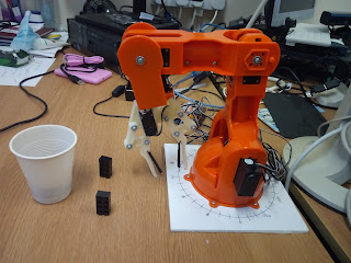
The new Tinkerkit Robot Arm
The first thing was to develop a mathematical solution to the problem. A simple trigonometric solution was opted for as providing the easiest method to understand and implement in code. As we are dealing with a 6 DoF arm, we can discount the Gripper and Wrist Rotation, leaving just the four angles to compute, i.e. Base Rotation, Shoulder Elevation, Elbow Angle and Wrist Angle. Using a servo driven arm further constrains the range of movement, as each joint is restricted to 180 degrees by the servo.

The original "homebrew" Arm
Once the maths had been worked out, then the corresponding code was developed using the Processing IDE. This was chosen because of its easy to use graphics capability, which was a boon in the development as it allowed the resulting movements to be viewed and modelled without potentially destroying the actual arm! Although Processing actually uses Java, the code was developed using functions and syntax which are also available in C++. This excludes the use of some of the nice functions available in Processing Java, but it makes it easy to port the code across to standard C++ when development is complete, for integration into a larger system. The screenshots below show how the code visualisation looked during development.
On the left of the screenshots is a view looking down on the arm from above, which gives a view of the arm in the X,Z plane, where X is horizontal (left / right) and Z is vertical in the screenshot (up / down). The larger red circle is the shoulder joint, so in Screenshot 1, the arm is all the way over to the left. The right hand side of the screenshot shows a side view of the arm, giving the Y,Z plane, where Y is the vertical axis both in the screenshot and for the actual arm, giving the height of the gripper above the surface the arm is mounted on, and Z is the distance of the gripper from the shoulder joint. Again, the shoulder joint is the larger red dot and the gripper is the smaller one. So, in this view we see the Shoulder joint, up at an angle we get to the Elbow joint, then moving along to the right we have the Wrist joint, then it's down to the Gripper. I think you should get the idea.
These first three screenshots show the arm in fully left rotation (X = -100), centre rotation (X = 0) and fully right (X = 100) rotation about the shoulder, whilst maintaining the Gripper height (Y = 50) and the Gripper distance from the shoulder (fully left Z = 0 : centre Z = 100 : fully right Z = 0). The numbers at the top of the screen are for monitoring and debugging the code during development, but you can see that the first 3 are the inputted values for X, Y, & Z. In this code the Gripper Angle is a given parameter which was entered as 0, corresponding to straight down. It was done this way to keep the solution code for the other joints simple, but will be calculated in the future phases of development when we come to integrate the code with the parameters obtained from a camera image.
 |
| Screenshot 1 - Arm to Left : X = -100; Z = 0 |
 |
| Screenshot 2 - Arm Central : X = 0; Z = 100 |
 |
| Screenshot 3 - Arm Right : X = 100 ; Z = 0 |


Comments
Post a Comment