Post 6 - Arms Race! – Part 2
Hi folks. It’s
been a busy time with one thing and another, but with Christmas now
only days away I thought I’d get one more post in before it.
Unfortunately I was thwarted in my attempt by my video camera
breaking down. Never the less I have soldiered on and used my 'phone
to shoot the video. This proved to be rather more time consuming as I
don't have a tripod mount & remote control for it like I do for
the video camera, so I had to do things several times over, pick the
best (i.e. least shaky) bits and edit them together to get one decent
stretch of video, but here we are now :-) .
Last time I posted
about fitting sensors to a cheap Maplin / OWI robot arm to give
feedback on what angle each of the joints was at. In this post I am
going to describe the other side of the operation, driving the motors.

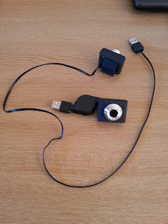
Getting ready to drop a building brick into a cup after picking it up from the the rectangle in the bottom left of the 'photo.
.You may recall from last time that I had acquired one of the above arms from ebay – where would we be without it, lol. Actually, I must confess that I have bought several of them for some project ideas I have in mind, due to finding them being sold very cheaply :-) .
The first step was
to design the circuitry for controlling the motors. You will recall
from my second posting that I have already built a motor control
circuit for the mobile platform, so I used this for the basis of the
design of the arm controller. The motors are once again controlled
using the ‘H’ bridge integrated circuit I used last time, with
the signals to drive the motors coming from an Arduino. As there are
5 motors in the arm, and each ‘H’ bridge chip can drive 2
bi-directional motors, then 3 chips are needed, leaving one ‘H’
bridge spare – although I’m sure I’ll find a use for it!
After some
consideration I decided that I could drive all 5 motors and read back
the analogue feedback using the same Arduino Nano, although it
wouldn’t leave a lot of spare capacity to do anything else. But,
then again, what else could it do? Driving the arm is enough, and the
Arduino Nano’s are cheap enough that it doesn’t matter dedicating
one to do this. It also has the advantage of a USB port, so the arm
can be given commands from a host computer via this.
So, having thought
about the design, and having previously experimented with the
analogue inputs, I went ahead and drew out a circuit. That was pretty
straight forward, the only thing to bear in mind was to ensure that
each motor drive had one of the Pulse Width Modulation (PWM) outputs
from the Arduino connected to it. As there are 6 available on the
Arduino Nano this wasn’t a problem.
Driving the motors
using PWM is different to the way I did it in the mobile platform. In
that case, the motors were just turned on or off in the desired
direction, and that’s fine for that application. For the arm,
though, to get the position of the joint controlled with any level of
accuracy, it’s necessary to be able to control the speed of the
motor and slow it down as it approaches it’s target position. This
is to counter the inertia from the weight of the motors, particularly
as they are mounted on the ends of ‘sticks’. Think of swinging a
hammer – it’s pretty much the same thing, a weight being moved on
the end of a stick. It’s difficult to get it to stop once you’ve
got it moving. It’s the same with the sections of the arm, so
that’s why we need to slow it down as it gets near to the desired
position to bring it to a controlled stop, hopefully right where we
want it to be.
For this circuit I
decided not to breadboard it as I had already tested the analogues,
and I knew the ‘H’ bridge circuit worked from building the mobile
platform, so I went ahead and built it straight onto strip board. I
socketed the Arduino Nano and the motor drive chips just in case I
got something wrong and had to replace them. It would be nice if
everything worked perfectly first time, but this is real life and
it’s never like that!
After spending far
longer building the board than I estimated it taking – my eyesight
isn’t what it was 30 years ago, lol – it was finally ready for
testing. I did the initial tests with some simple code that just
moved the motors forwards and backwards a little, just to check that
everything was wired correctly and was working as expected. Needless
to say, it wasn’t, and I had to resort to doing some fault finding.
I had a wire in the wrong place and also I’d gotten a splash of
solder across two adjacent tracks! No permanent damage done though,
and soon fixed. Second time it worked fine. Success!

Photo of the completed board with one drive chip fitted for testing
That, however, was
the easy part. Next up was the code to make it perform as a robot arm
should. This consists of three basic parts – reading the position
of the joints at an instance in time, getting new position
information for where each joint is desired to be, and moving the
joints to the new positions under control. As I had already developed
code to perform these operations, namely reading the analogue inputs
and scaling them in my previous post, and getting desired position
information from the USB serial link (see my Head Project post) then
I used those codes for the basis of what I needed for the arm. I also
had code for moving the motors in On / Off mode, which I developed
for the Mobile Robot Base project, so I decided to extend that by
writing a PWM 'front end' which would take in a desired value of
motor power and convert this into a value of PWM to pass into the
motor driver code. The driver code was then modified to use the power
value input to it to drive the motors, instead of being just on or
off.
To get the angle to
move each joint to via the USB interface, I took the code I had
developed for the Robot Head project and extended it to accept 5
values instead of two. I took the opportunity to tidy up the code and
make it more generic, so that it will form the basis of, and be a
step nearer to, the general purpose Low Level Interface Protocol I'm
developing for serial communications between a PC and Arduino, aimed
at driving the different modules I'm building.
For the control of
the positioning of each joint to the angle specified via the USB
link, I decided to implement PID control loops. PID loops are a
technique used in Control & Automation to get a good level of
accuracy of a parameter under control against the required set point
for it (desired position). The downside is that each loop needs to be
'tuned' for optimal results, which is largely a matter of trial &
error in adjusting the control parameters.
Whilst developing
the code for the arm control, I also decided that it would be better
to have a general purpose scheduling code, instead of having timing
functions repeated in each of the code blocks, so I developed code
for a generic Task Scheduler. This allows me to set up accurately
timed 'slots' in which I can place calls to the functions I want to
run. For example, if I have some functions that I want to run every
10mS (milli Seconds), then in my scheduler I create a 10mS time slot
and place the function calls in there for the functions I want to run
every 10mS. This has a couple of benefits. Firstly, it cuts down on
the overall amount of code, as otherwise each function would have to
have timing code in it to do this. Secondly, it makes the overall
program more efficient by only checking the timing once in each loop
around of the main loop. It also allows me to easily segregate the
functions which run at different times, making the code more readable
and thus easier to maintain. So, all in all, I reckoned it was worth
spending the time developing the Scheduler as it will be used in
pretty much all of my future developments.

Completed board hooked up for testing

View of the test setup
With all of the code
modules developed, it was time to try them out. I've posted a short
video below of the arm in action after some de-bugging of the code. I
haven't tuned the control loops yet to get the best performance, and
you can see what happens on the Wrist and Elbow joints. They
overshoot the target position then correct the error by driving in
the opposite direction. In the case of the wrist, it does this a
couple of times before it settles out at the set point. Some tuning
of the control parameters will be needed to eliminate that, but on
the whole it works quite well. The accuracy I'm getting is better
than + / - 0.5 degrees of the measured position (read from the pots)
against the desired position entered as a set point on the computer
keyboard. Pretty good, I think, for a cheap arm with some low cost
potentiometer feedback!
So, what's next?
Well, tuning the control loops for one thing, lol. Eliminating that
overshoot & recovery will give a more accurate level of control.
Also I need to write some more code to make the control more robust,
such as preventing the joints from moving into positions which they
aren't allowed to. This will stop the arm movement interfering with
the mechanics and feedback linkages on the potentiometers. I'm also
adding some error detection too, so if a joint is demanded to move
but is detected as not moving, then I can cut the power before
burning out a motor or the driver chips! Aside from that, some sort
of GUI (Graphical User Interface) on the PC will be better than
typing in the movements individually, so that the arm can be
programmed to perform a sequence of movements, like the large
industrial ones.
I am also thinking
of making what I've done available, possibly producing a kit with
printed circuit boards and wire loom, to allow people to build one
themselves if there's enough interest. If you would be interested in
this, please let me know by using the 'Contact Me' form in the drop
down menu at the top left of the blog.
In the meantime,
That's All Folks!


Comments
Post a Comment